* Remove dead (unsafe) link

Removed as noted in <https://github.com/SoftFever/OrcaSlicer/issues/9731>

* Add new calibration site link

* remove link entirely as per conversation with @ianalexis

Related to https://github.com/SoftFever/OrcaSlicer/pull/9761
23 KiB
Important
After completing the calibration process, remember to create a new project in order to exit the calibration mode.
Flow rate
Warning
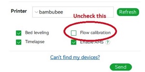
For Bambulab X1/X1C users, make sure you do not select the 'Flow calibration' option.
Important
PASS 1 and PASS 2 follow the older flow ratio formula
FlowRatio_old*(100 + modifier)/100. YOLO (Recommended) and YOLO (perfectist version) use a new system that is very simpleFlowRatio_old±modifier.

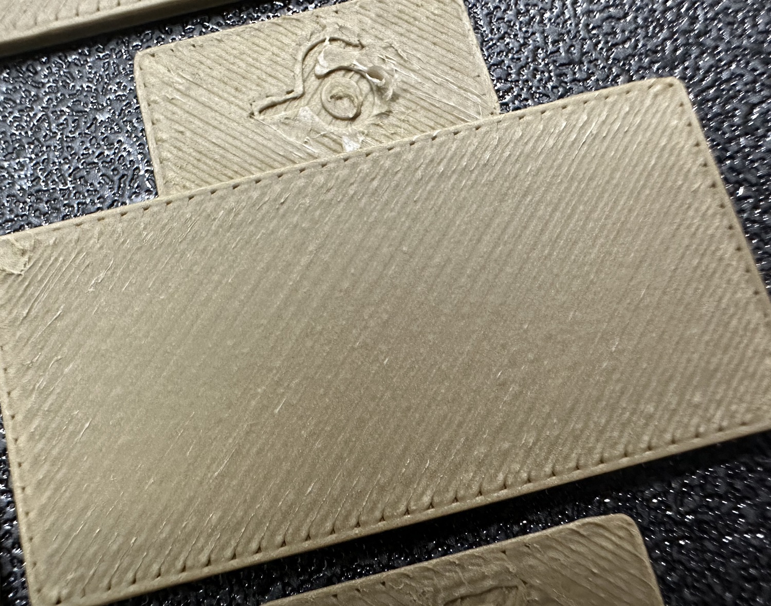
Calibrating the flow rate involves a two-step process. Steps
-
Select the printer, filament, and process you would like to use for the test.
-
Select
Pass 1in theCalibrationmenu -
A new project consisting of nine blocks will be created, each with a different flow rate modifier. Slice and print the project.
-
Examine the blocks and determine which one has the smoothest top surface.
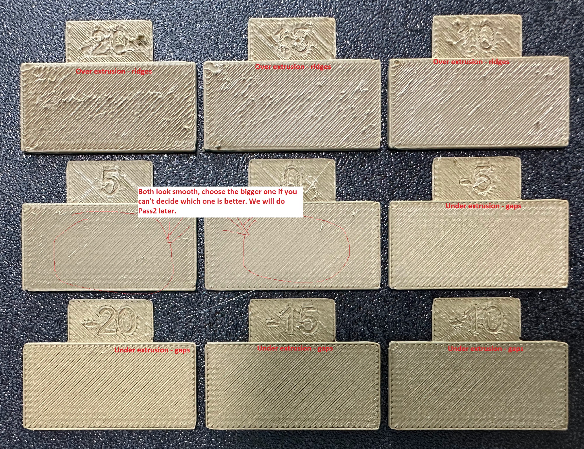
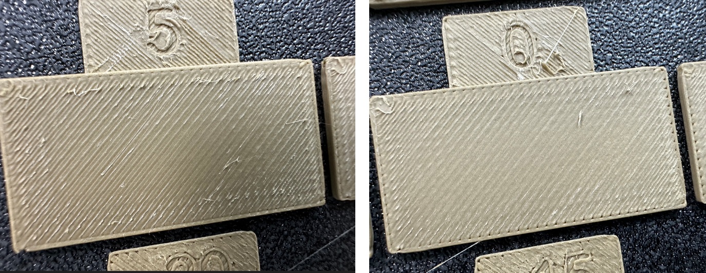
-
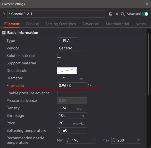
Update the flow ratio in the filament settings using the following equation:
FlowRatio_old*(100 + modifier)/100. If your previous flow ratio was0.98and you selected the block with a flow rate modifier of+5, the new value should be calculated as follows:0.98x(100+5)/100 = 1.029.** Remember** to save the filament profile. -
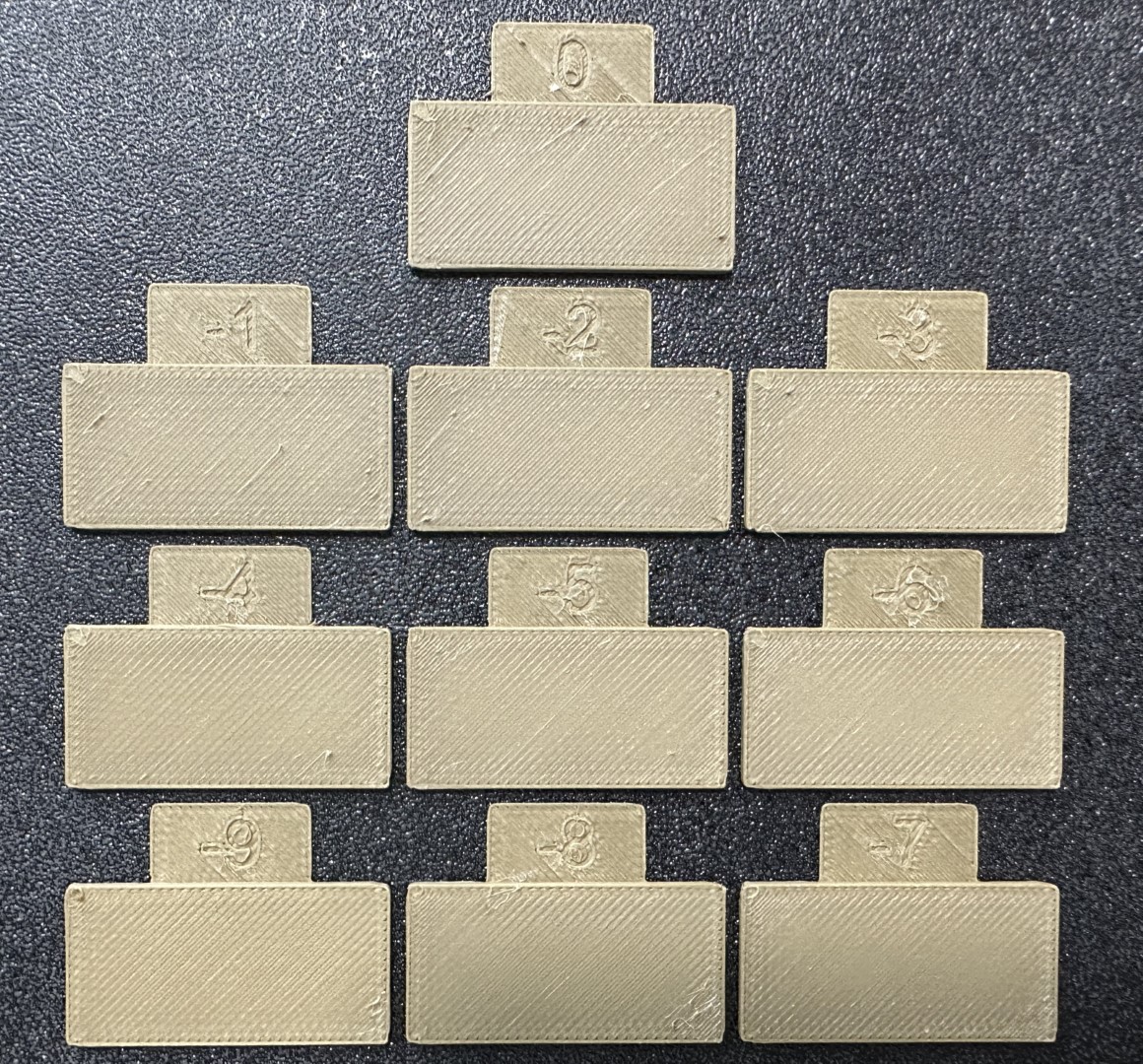
Perform the
Pass 2calibration. This process is similar toPass 1, but a new project with ten blocks will be generated. The flow rate modifiers for this project will range from-9 to 0. -
Repeat steps 4. and 5. In this case, if your previous flow ratio was 1.029 and you selected the block with a flow rate modifier of -6, the new value should be calculated as follows:
1.029x(100-6)/100 = 0.96726. Remember to save the filament profile.
Pressure Advance
Orca Slicer includes three approaches for calibrating the pressure advance value. Each method has its own advantages and disadvantages. It is important to note that each method has two versions: one for a direct drive extruder and one for a Bowden extruder. Make sure to select the appropriate version for your test.
Warning
For Marlin: Linear advance must be enabled in firmware (M900). Not all printers have it enabled by default.
Warning
For Bambulab X1/X1C users, make sure you do not select the 'Flow calibration' option when printings.
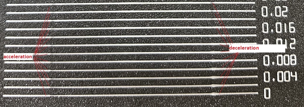
Line method
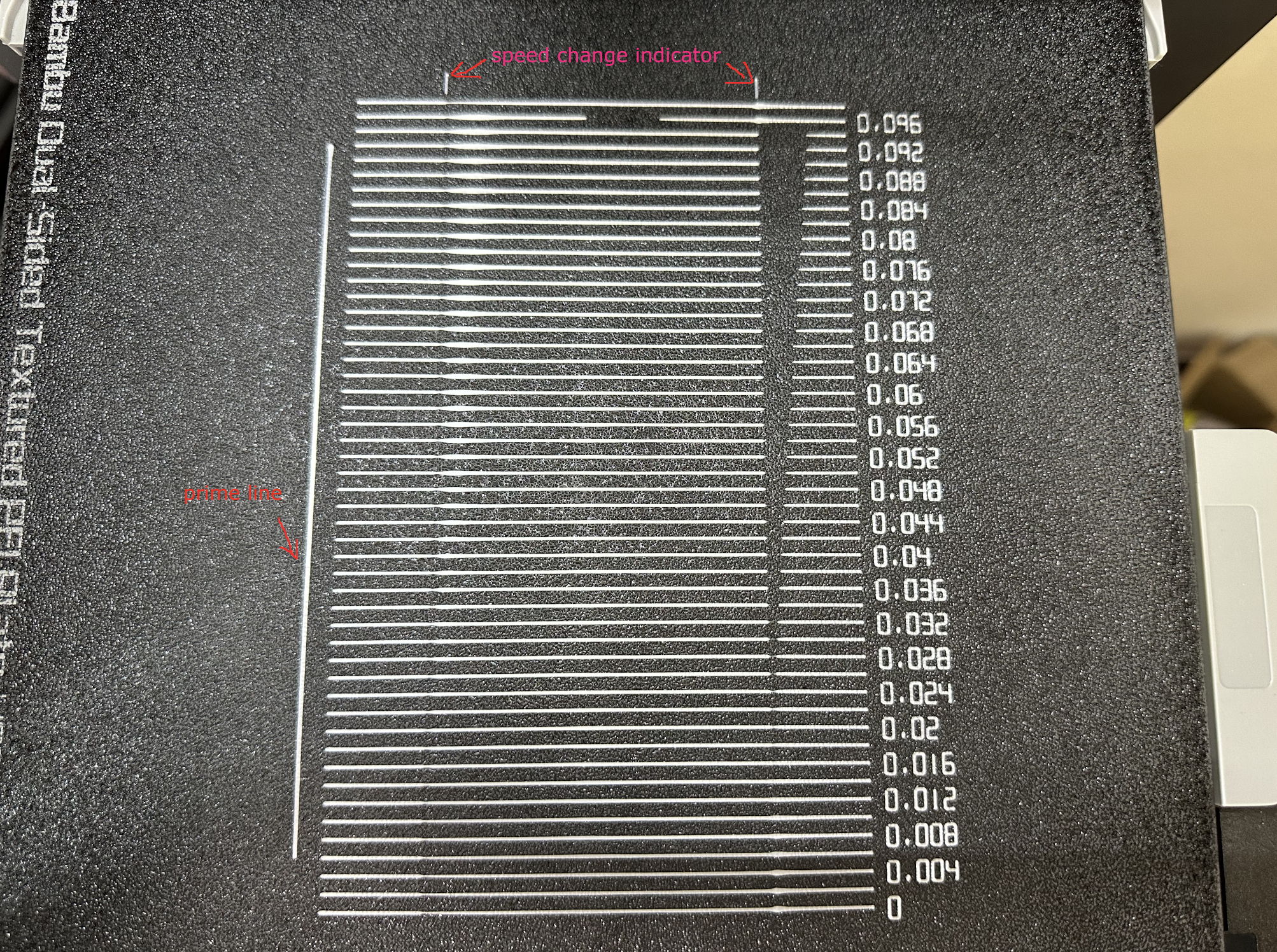
The line method is quick and straightforward to test. However, its accuracy highly depends on your first layer quality. It is suggested to turn on the bed mesh leveling for this test. Steps:
- Select the printer, filament, and process you would like to use for the test.
- Print the project and check the result. You can select the value of the most even line and update your PA value in the filament settings.
- In this test, a PA value of
0.016appears to be optimal.

Pattern method
The pattern method is adapted from Andrew Ellis' pattern method generator, which was itself derived from the Marlin pattern method developed by Sineos.
Instructions for using and reading the pattern method are provided in Ellis' Print Tuning Guide, with only a few Orca Slicer differences to note.
Test configuration window allow user to generate one or more tests in a single projects. Multiple tests will be placed on each plate with extra plates added if needed.
- Single test

- Batch mode testing (multiple tests on a sinle plate)

Once test generated, one or more small rectangular prisms could be found on the plate, one for each test case. This object serves a few purposes:
- The test pattern itself is added in as custom G-Code at each layer, same as you could do by hand actually. The rectangular prism gives us the layers in which to insert that G-Code. This also means that you'll see the full test pattern when you move to the Preview pane:

- The prism acts as a handle, enabling you to move the test pattern wherever you'd like on the plate by moving the prism
- Each test object is pre-configured with target parameters which are reflected in the objects name. However, test parameters may be adjusted for each prism individually by referring to the object list pane:

Next, Ellis' generator provided the ability to adjust specific printer, filament, and print profile settings. You can make these same changes in Orca Slicer by adjusting the settings in the Prepare pane as you would with any other print. When you initiate the calibration test, Ellis' default settings are applied. A few things to note about these settings:
- Ellis specified line widths as a percent of filament diameter. The Orca pattern method does the same to provide its suggested defaults, making use of Ellis' percentages in combination with your specified nozzle diameter
- In terms of line width, the pattern only makes use of the
DefaultandFirst layerwidths - In terms of speed, the pattern only uses the
First layer speed -> First layerandOther layers speed -> Outer wallspeeds - The infill pattern beneath the numbers cannot be changed becuase it's not actually an infill pattern pulled from the settings. All of the pattern G-Code is custom written, so that "infill" is, effectively, hand-drawn and so not processed through the usual channels that would enable Orca to recognize it as infill
Tower method
The tower method may take a bit more time to complete, but it does not rely on the quality of the first layer. The PA value for this test will be increased by 0.002 for every 1 mm increase in height. (NOTE 0.02 for Bowden) Steps:
- Select the printer, filament, and process you would like to use for the test.
- Examine each corner of the print and mark the height that yields the best overall result.
- I selected a height of 8 mm for this case, so the pressure advance value should be calculated as
PressureAdvanceStart+(PressureAdvanceStep x measured)example:0+(0.002 x 8) = 0.016.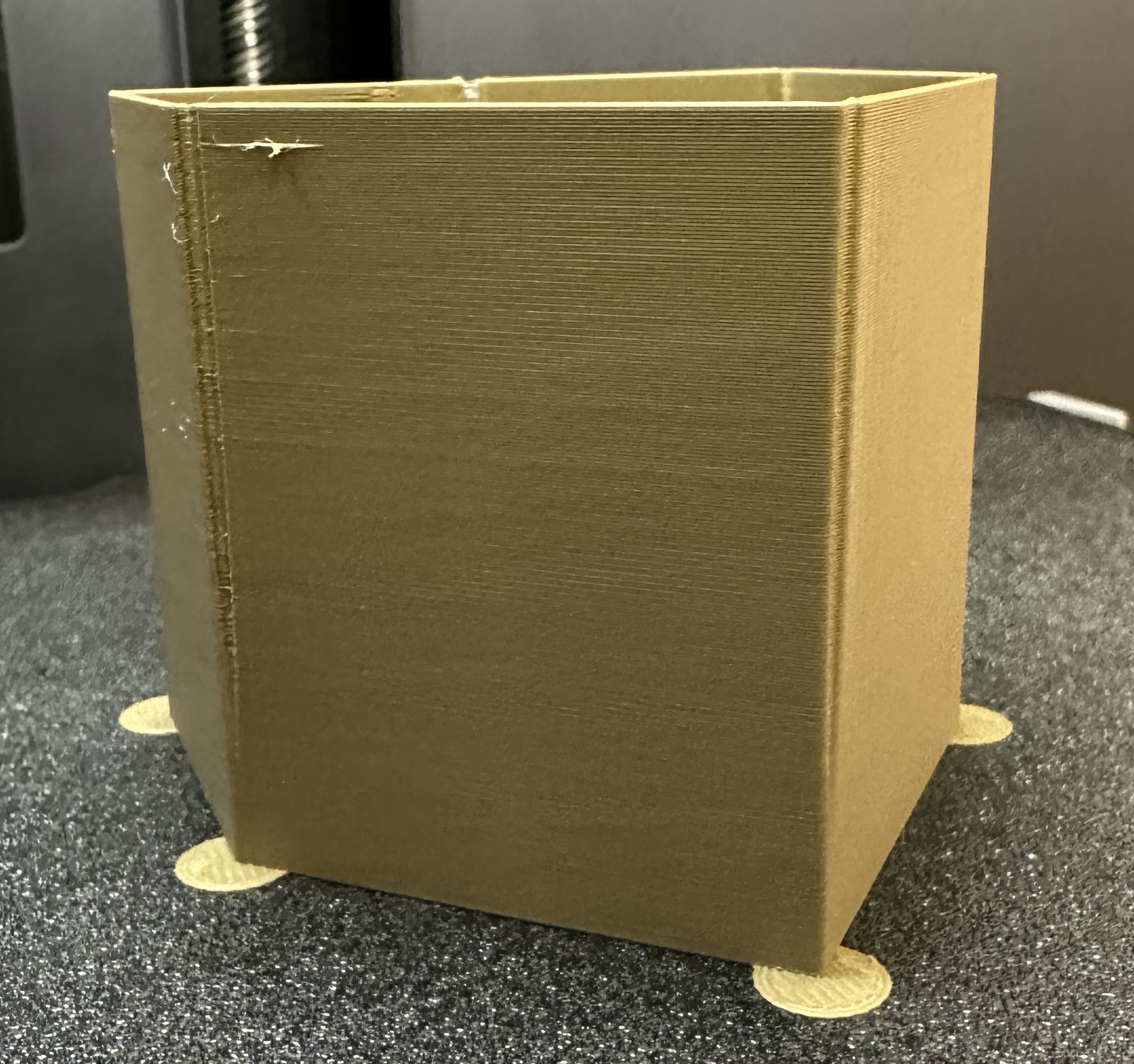
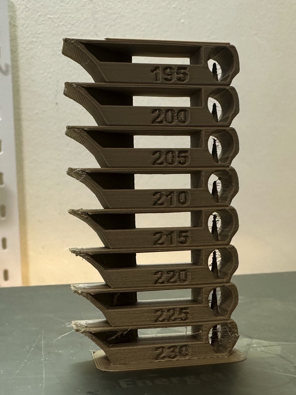
Temp tower
 Temp tower is a straightforward test. The temp tower is a vertical tower with multiple blocks, each printed at a different temperature. Once the print is complete, we can examine each block of the tower and determine the optimal temperature for the filament. The optimal temperature is the one that produces the highest quality print with the least amount of issues, such as stringing, layer adhesion, warping (overhang), and bridging.
Retraction test
 This test generates a retraction tower automatically. The retraction tower is a vertical structure with multiple notches, each printed at a different retraction length. After the print is complete, we can examine each section of the tower to determine the optimal retraction length for the filament. The optimal retraction length is the shortest one that produces the cleanest tower.
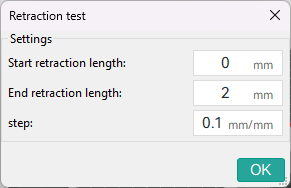 In the dialog, you can select the start and end retraction length, as well as the retraction length increment step. The default values are 0mm for the start retraction length, 2mm for the end retraction length, and 0.1mm for the step. These values are suitable for most direct drive extruders. However, for Bowden extruders, you may want to increase the start and end retraction lengths to 1mm and 6mm, respectively, and set the step to 0.2mm.
Note: When testing filaments such as PLA or ABS that have minimal oozing, the retraction settings can be highly effective. You may find that the retraction tower appears clean right from the start. In such situations, setting the retraction length to 0.2mm - 0.4mm using Orca Slicer should suffice.
On the other hand, if there is still a lot of stringing at the top of the tower, it is recommended to dry your filament and ensure that your nozzle is properly installed without any leaks.

Orca Tolerance Test
This tolerance test is specifically designed to assess the dimensional accuracy of your printer and filament. The model comprises a base and a hexagon tester. The base contains six hexagon hole, each with a different tolerance: 0.0mm, 0.05mm, 0.1mm, 0.2mm, 0.3mm, and 0.4mm. The dimensions of the hexagon tester are illustrated in the image.

You can assess the tolerance using either an M6 Allen key or the printed hexagon tester.


Advanced Calibration
Max Volumetric speed
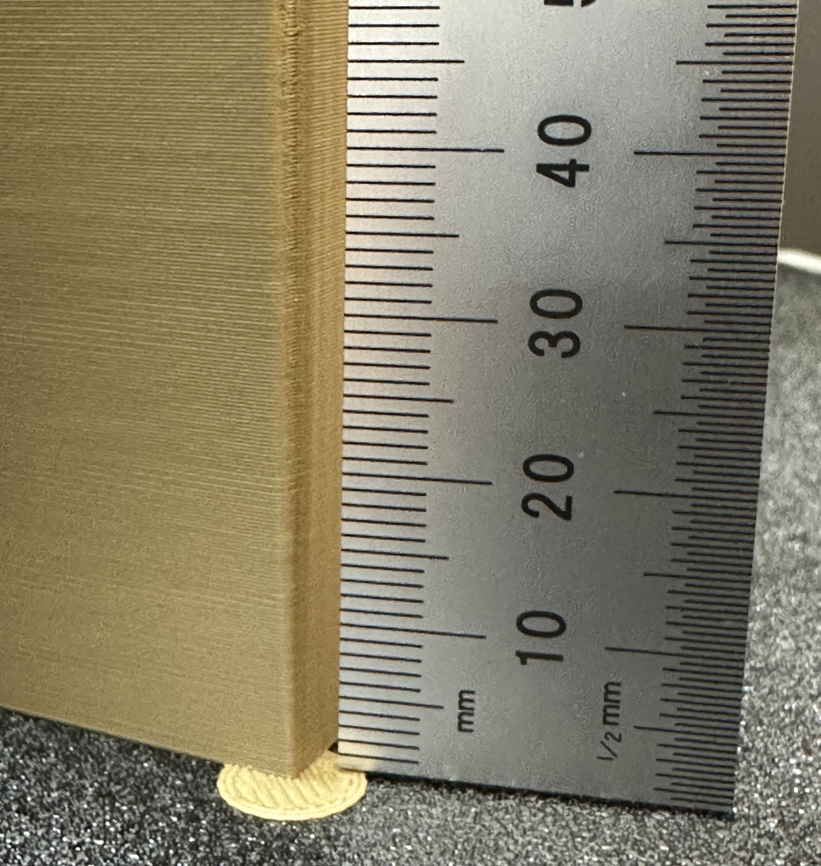
This is a test designed to calibrate the maximum volumetric speed of the specific filament. The generic or 3rd party filament types may not have the correct volumetric flow rate set in the filament. This test will help you to find the maximum volumetric speed of the filament.
You will be promted to enter the settings for the test: start volumetric speed, end volumentric speed, and step. It is recommended to use the default values (5mm³/s start, 20mm³/s end, with a step of 0.5), unless you already have an idea of the lower or upper limit for your filament. Select "OK", slice the plate, and send it to the printer.
Once printed, take note of where the layers begin to fail and where the quality begins to suffer. Pay attention to changes from matte to shiny as well.

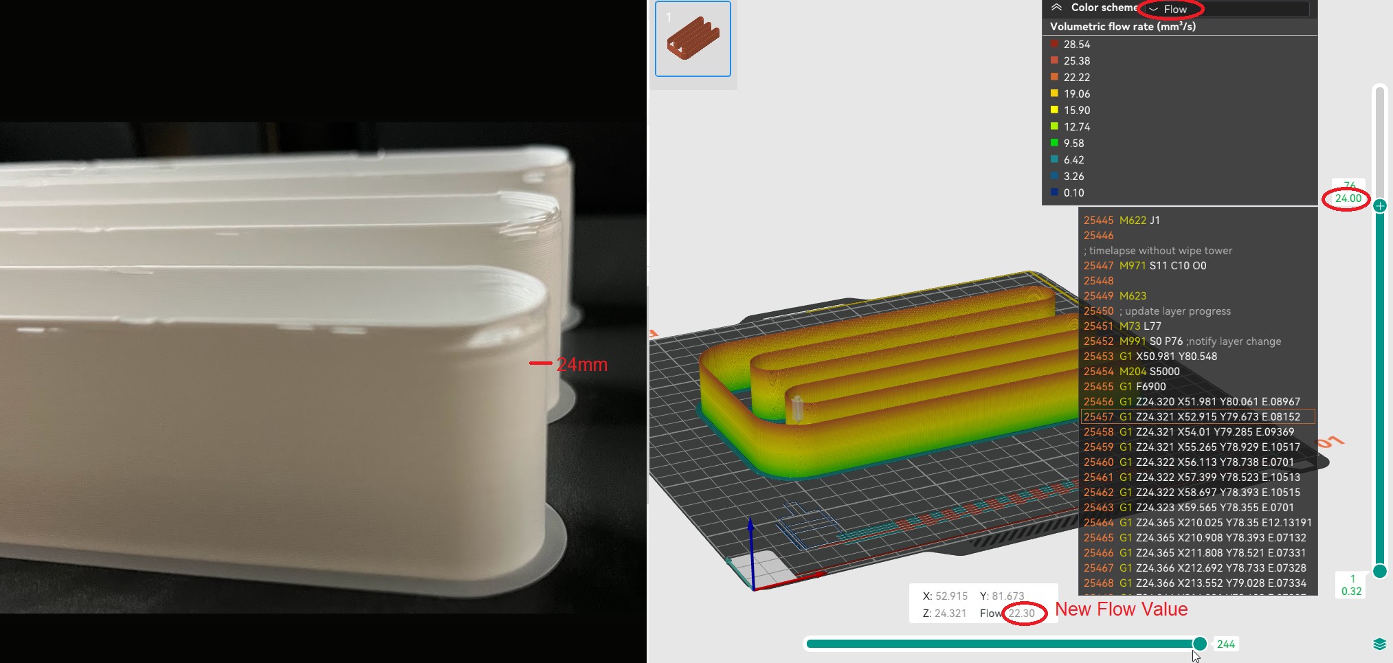
Using calipers or a ruler, measure the height of the print at that point. Use the following calculation to determine the correct max flow value: start + (height-measured * step) . For example in the photo below, and using the default setting values, the print quality began to suffer at 19mm measured, so the calculation would be: 5 + (19 * 0.5) , or 13mm³/s using the default values. Enter your number into the "Max volumetric speed" value in the filament settings.

You can also return to OrcaSlicer in the "Preview" tab, make sure the color scheme "flow" is selected. Scroll down to the layer height that you measured, and click on the toolhead slider. This will indicate the max flow level for your filmanet.
Note
You may also choose to conservatively reduce the flow by 5-10% to ensure print quality.
Input Shaping
During high-speed movements, vibrations can cause a phenomenon called "ringing," where periodic ripples appear on the print surface. Input Shaping provides an effective solution by counteracting these vibrations, improving print quality and reducing wear on components without needing to significantly lower print speeds.
Klipper
Resonance Compensation
The Klipper Resonance Compensation is a set of Input Shaping modes that can be used to reduce ringing and improve print quality.
Ussualy the recommended values modes are MZV or EI for Delta printers.
-
Pre-requisites:
- In OrcaSlicer, set:
- Acceleration high enough to trigger ringing (e.g., 2000 mm/s²).
- Speed high enough to trigger ringing (e.g., 200 mm/s).
Note
These settings depend on your printer's motion ability and the filament's max volumetric speed. If you can't reach speeds that cause ringing, try increasing the filament's max volumetric speed (avoid materials below 10 mm³/s).
- Jerk Klipper Square Corner Velocity to 5 or a high value (e.g., 20).
- In printer settigs:
- Set the Shaper Type to
MZVorEI.SET_INPUT_SHAPER SHAPER_TYPE=MZV - Disable Minimun Cruise Ratio with:
SET_VELOCITY_LIMIT MINIMUM_CRUISE_RATIO=0
- Set the Shaper Type to
- Use an opaque, high-gloss filament to make the ringing more visible.
- In OrcaSlicer, set:
-
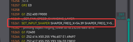
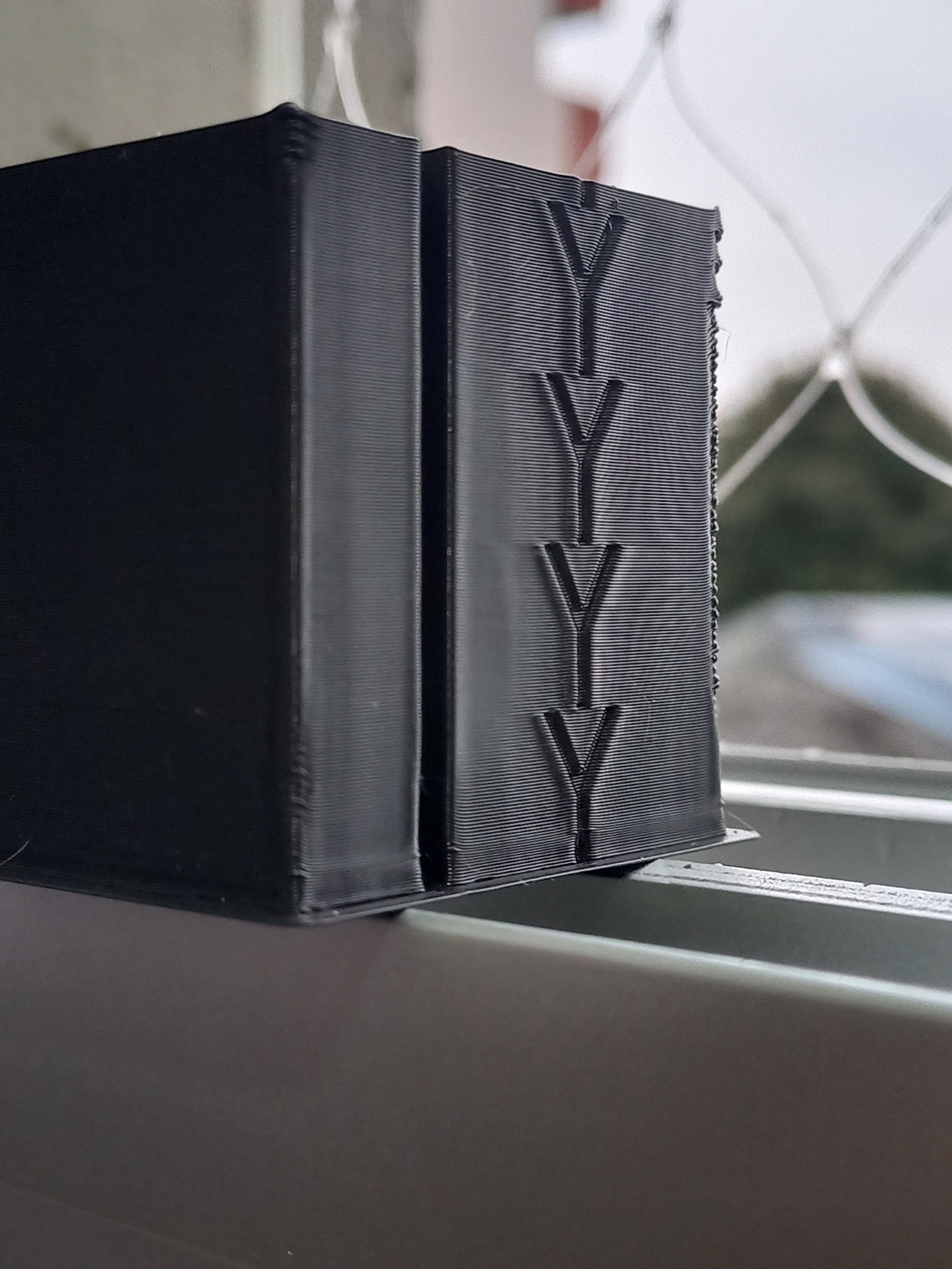
Print the Input Shaping Frequency test with a range of frequencies.

- Measure the X and Y heights and read the frequency set at that point in Orca Slicer.

- If not a clear result, you can measure a X and Y min and max acceptable heights and repeat the test with that min and max value.
Note: There is a chance you will need to set higher than 60Hz frequencies. Some printers with very rigid frames and excellent mechanics may exhibit frequencies exceeding 100Hz.
-
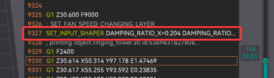
Print the Damping test setting your X and Y frequency to the value you found in the previous step.

- Measure the X and Y heights and read the damping set at that point in Orca Slicer.
Note: Not all Resonance Compensation modes support damping
-
Restore your 3D Printer settings to avoid keep using high acceleration and jerk values.
-
Save the settings
- You need to go to the printer settings and set the X and Y frequency and damp to the value you found in the previous step.
Marlin
ZV Input Shaping
ZV Input Shaping introduces an anti-vibration signal into the stepper motion for the X and Y axes. It works by splitting the step count into two halves: the first at half the frequency and the second as an "echo," delayed by half the ringing interval. This simple approach effectively reduces vibrations, improving print quality and allowing for higher speeds.
-
Pre-requisites:
- In OrcaSlicer, set:
- Acceleration high enough to trigger ringing (e.g., 2000 mm/s²).
- Speed high enough to trigger ringing (e.g., 200 mm/s).
Note
These settings depend on your printer's motion ability and the filament's max volumetric speed. If you can't reach speeds that cause ringing, try increasing the filament's max volumetric speed (avoid materials below 10 mm³/s).
- Jerk
- If using Classic Jerk use a high value (e.g., 20).
- If using Junction Deviation (new Marlin default mode) this test will use 0.25 (high enough to most printers).
- Use an opaque, high-gloss filament to make the ringing more visible.
- In OrcaSlicer, set:
-
Print the Input Shaping Frequency test with a range of frequencies.
- Measure the X and Y heights and read the frequency set at that point in Orca Slicer.

- If not a clear result, you can measure a X and Y min and max acceptable heights and repeat the test with that min and max value.
Note: There is a chance you will need to set higher than 60Hz frequencies. Some printers with very rigid frames and excellent mechanics may exhibit frequencies exceeding 100Hz.
-
Print the Damping test setting your X and Y frequency to the value you found in the previous step.
- Measure the X and Y heights and read the damping set at that point in Orca Slicer.


-
Restore your 3D Printer settings to avoid keep using high acceleration and jerk values.
- Reboot your printer.
- Use the following G-code to restore your printer settings:
M501 -
Save the settings
- You need to go to the printer settings and set the X and Y frequency and damp to the value you found in the previous step.
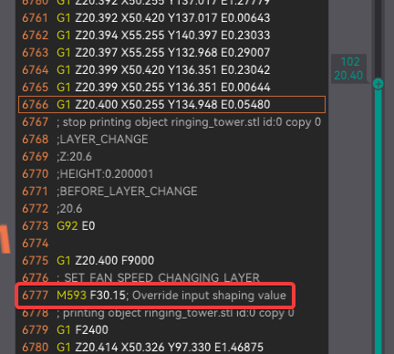
- Use the following G-code to set the frequency:
M593 X F#Xfrequency D#XDamping
M593 Y F#Yfrequency D#YDamping
M500
Example
M593 X F37.25 D0.16
M593 Y F37.5 D0.06
M500
Fixed-Time Motion
TODO This calibration test is currently under development. See the Marlin documentation for more information.
Junction Deviation
Junction Deviation is the default method for controlling cornering speed in MarlinFW printers. Higher values result in more aggressive cornering speeds, while lower values produce smoother, more controlled cornering. The default value in Marlin is typically set to 0.08mm, which may be too high for some printers, potentially causing ringing. Consider lowering this value to reduce ringing, but avoid setting it too low, as this could lead to excessively slow cornering speeds.
-
Pre-requisites:
- Check if your printer has Junction Deviation enabled. You can do this by sending the command
M503to your printer and looking for the lineJunction deviation: 0.25. - In OrcaSlicer, set:
- Acceleration high enough to trigger ringing (e.g., 2000 mm/s²).
- Speed high enough to trigger ringing (e.g., 100 mm/s).
- Use an opaque, high-gloss filament to make the ringing more visible.
- Check if your printer has Junction Deviation enabled. You can do this by sending the command
-
You need to print the Junction Deviation test.

- Measure the X and Y heights and read the frequency set at that point in Orca Slicer.
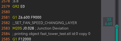
- It’s very likely that you’ll need to set values lower than 0.08 mm, as shown in the previous example. To determine a more accurate maximum JD value, you can print a new calibration tower with a maximum value set at the point where the corners start losing sharpness.

- Measure the X and Y heights and read the frequency set at that point in Orca Slicer.


-
Save the settings
- Set your Maximun Junction Deviation value in [Printer settings/Motion ability/Jerk limitation].
- Use the following G-code to set the mm:
M205 J#JunctionDeviationValue
M500
Example
M205 J0.012 M500- Recompile your MarlinFW
- In Configuration.h uncomment and set:
#define JUNCTION_DEVIATION_MM 0.012 // (mm) Distance from real junction edge- Check Classic Jerk is disabled (commented).
//#define CLASSIC_JERK
VFA
Vertical Fine Artifacts (VFA) are small artifacts that can occur on the surface of a 3D print, particularly in areas where there are sharp corners or changes in direction. These artifacts can be caused by a variety of factors, including mechanical vibrations, resonance, and other factors that can affect the quality of the print. Because of the nature of these artifacts the methods to reduce them can be mechanical such as changing motors, belts and pulleys or with advanced calibrations such as Jerk/Juction Deviation corrections or Input Shaping.
Credits:
- The Flowrate test and retraction test is inspired by SuperSlicer.
- The PA Line method is inspired by K-factor Calibration Pattern.
- The PA Tower method is inspired by Klipper.
- The temp tower model is remixed from Smart compact temperature calibration tower.
- The max flowrate test was inspired by Stefan (CNC Kitchen), and the model used in the test is a remix of his Extrusion Test Structure.
- ZV Input Shaping is inspired by Marlin Input Shaping and Ringing Tower 3D STL.
- ChatGPT ;)